
For an average computer user, the motherboard with its complex design, confusing acronyms, and unfamiliarity elicits a kind of cosmic horror that even Lovecraft would be proud of. And with dozens of models available for most platforms, it can be tough to make sense of the modern motherboard unless you are passionate about PC hardware. But understanding the motherboard can be a rewarding experience, as the motherboard is a component that’s common to all computers. There’s a motherboard (often called the logic board or MOBO) sitting in every computer system, from smartphones and smart devices to room-sized workstations. It forms the foundation of the modern computer in a sense, and having good knowledge about the motherboard can not only help you learn how a computer works, but also understand the complex relations that PC components have with each other.
What Is a Motherboard: Guide to All Ports and Connections (2022)
What we are trying to do through this article is give you a detailed breakdown of the motherboard structure by covering all of the major ports, headers, and slots that are common on today’s hardware. This breakdown, we believe, will help uncover the genius of the modern motherboard. It will assist you not only in understanding the motherboard better but also giving you a new level of appreciation for the hardware.
Note: This is the first of the many computer basics articles that Beebom will be publishing soon. So if you are interested in learning more about PC hardware, keep an eye out on our website for similar content.
Defining a Computer Motherboard
Simply put, a motherboard is a giant Printed Circuit Board (PCB) that connects all your other PC components like the CPU, GPU, RAM and storage together. Think of it like the nervous system or the circulatory system of the computer. The motherboard makes sure that all these components are speaking the same language and that the systems all run together properly. It does this simply by controlling the amount of electricity and data that passes through the circuit board. This is done through thousands of small strips of copper wire that are sandwiched between the multiple layers substrate that make up the motherboard. If you look close enough at the motherboard, you can see some traces that run along the top layer.
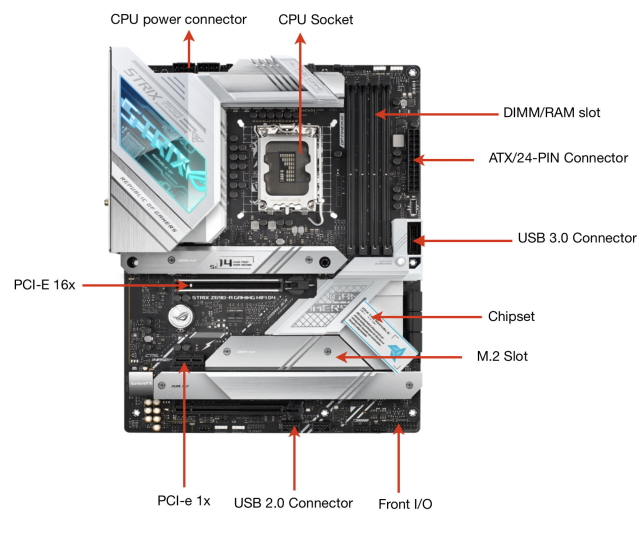
Below we have an image of a modern motherboard, particularly, a modern ATX board. Even though it’s of a specific form factor (ATX), the general design of most modern motherboards is very similar in terms of connections and design philosophy. So for the purposes of this article it should do.

A Brief History of the Motherboard
In our popular conception of a computer, the motherboard has always played an important part. It’s image has long been associated with the complex, mysterious innards of the system. But as we will explore in this section, the modern motherboard, while gives the impression of being an old concept, was actually invented long after the first computer.
Early computers were more complex than modern machines in terms of parts and consisted of multiple circuits boards connected to each other by a backplane, a set of interconnected sockets. What this meant was that CPU, memory, and peripherals were all housed in their individual boards.

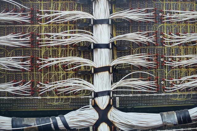
This changed, however, with the coming of microprocessors. As microprocessors got more powerful, they were able to execute workloads that were earlier done by dedicated hardware. This made it more economical for computer manufacturers to produce a single large board with all the functionality built in rather than build smaller dedicated circuit boards and connect it all together through a backplane.

The IBM Personal Computer (1981) featured the first motherboard as we know it. At first, this component was called a planar and, at the beginning of its creation, went through many additional names. However, the term that stuck was the “Motherboard” as the board essentially acted like a mother to all the other computer components. And it’s the main reason why smaller boards connected to the motherboard are sometimes known as daughterboards.
IBM PC’s motherboard housed the computer’s CPU and RAM, provided audio as well as many other essential functions, supplied ports for the keyboard and cassette tape. This board even had expansion slots for add-on cards as well as a system called a bus to manage these information flows.
The IBC PC was a revolutionary machine that changed the future of computing. Maybe this is why the original IBM PC, with its simplicity and openness, set the standard for many computer hardware specifications in “IBM-compatible” computers, and its famous moniker “PC” came to be the singular word to describe the computer for years to come.
Different Sizes of Motherboards
The motherboard might be much simpler than the giant computers of the past, but at a first glance, still looks like a complex object, and to be honest it is. It’s a labyrinth of circuitry that is both overwhelming and fascinating. But when it comes to motherboard sizes or types, the situation is much more comprehensible.
While historically motherboards came in different sizes like IBM’s Baby ATX or Intel’s NLX boards, the vast majority of today’s consumer motherboards come in one of three sizes: ATX, Micro-ATX, and Mini-ITX.

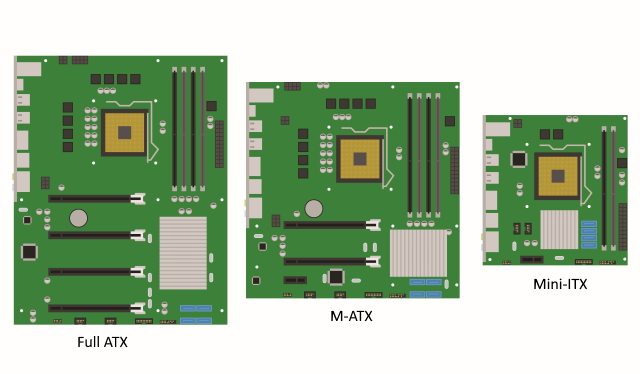
The ATX platform is the most popular of them all and has been the industry standard for a while now. It delivers a lot of flexibility when it comes to expansion and upgrading, which makes this form-factor the preferred one for gamers and other PC enthusiasts. Mini-ITX, on the other hand, is the smallest of the bunch, and is usually used in compact PC builds.
Finally, the Micro-ATX form factor splits the two in the middle and offers you some flexibility when it comes to PCI-e and RAM expansion while keeping the overall size smaller than full-ATX motherboard. Furthermore, one might also come across E-ATX motherboards, which are larger than full-ATX, but those are primarily used in workstation systems. Other form factors do still exist like the Mini-STX, but they are so rare that one can hardly ever find them in retail stores.
Motherboard Ports and Connections
Over the years, the number of different ports and their designs have changed due to evolving technology. Older and outdated ports like the Serial port have given way to USB and even relatively newer standards like SATA are being replaced for newer technologies like M.2. In the ever evolving face of computer technology, everything is transient. But that doesn’t mean that its useless to know the ports of today.
These ports form the fundamentals of desktop computer, and we have listed (and explained) some of the most important connection that you might find on your motherboard. To make it easier to understand, one can segregate motherboard ports into three distinct categories:
- Slots/ Ports: These are usually raised ports that arise from the motherboard and can accommodate a variety of hardware components. Depending on the age of your motherboard, the major slots and ports you will find can be – PCIe (Peripheral Component Interconnect), RAM (Random Access Memory), SATA and M.2. Older motherboards might also have other ports like AGP (accelerated graphics ports), which have been almost entirely replaced by PCIe in modern motherboards.
- Sockets: These are openings on the motherboard that allow users to install component pieces directly onto the motherboard. The CPU socket is the most notable example of this.
- Connections: Connections provide power via your power supply to your component parts. These are often pin connections, some of which are placed in raised sockets (via ATX connectors), while others are bare like the Power and Reset pins.
CPU Sockets
We are going to start this dissection with the most important part of the motherboard, which is the CPU socket, also known as the CPU slot. It’s a part of the motherboard that contains the necessary terminals and parts to hold the CPU in place. As you can see in the image below, this socket is easy to spot on most motherboards as it has a distinct design and covers a large surface area.


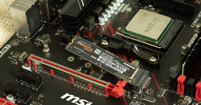
CPU sockets these days come in two variants — LGA (Land Grid Array) and PGA (Pin Grid Array). What differentiates these two is essentially the arrangement of contact pins. Depending on the type of processor, these pins are either on the socket or on the underside of the CPU die itself. In LGA, for example, you have contact plates on both the underside of the processor and the CPU socket.
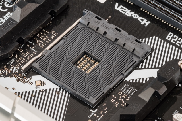
In PGA, which is normally used by AMD, small pins are located on the underside of the CPU, which directly go into small holes in the CPU socket. The PGA CPU socket is highlighted in the image above.
There are also various versions of sockets within the two socket types, and different sockets affect the output performance of the CPU. For example, within the LGA socket type, Intel offers many variants with a variety of different pin setups. All newer motherboard usually come with the latest socket type that allow you to pair the motherboard with newer more powerful CPUs.
For example, as mentioned above, the ASUS motherboard in our example comes with an LGA 1700 socket (the number represents how many pins are in this socket) that works with the 12th-Gen Intel Core processors, enabling you to use Intel’s latest and greatest hardware. In the following image, you can see the Intel LGA 2011 socket up close.
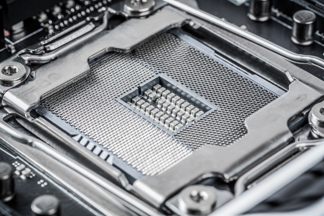
In general, the more capable the CPU (in terms of the number of cores, amount of cache, etc.), the more pins will be found in the socket. This was the main reason why the Intel HEDT processor lineup used the LGA 2011 socket, which had almost twice the number of pins compared to the prevailing LGA 1151 socket at the time. The larger number of pins, for example, can allow the processor to access more power from the power supply as more power delivery pins can be allocated to the processor.
However, an increase in pins is not the only way to gauge a performance increase. For example, AMD has stayed on the same 1331 pin layout since Ryzen 1, which was released in 2017, but has seen remarkable increase in performance over the generations.
RAM Slots
The second important part of the motherboard that we will talk about are the RAM slots. These are usually located right next to the CPU socket. Random access memory (RAM) is essentially a form of very fast memory (can be several times faster than SSD) that stores data, so that applications can be accessed quickly.
RAM is different from storage like SSDs or HDDs as it’s volatile, which means it loses information when the power is turned off or when the computer is reset. Programs and applications, ranging from word processors to games, all require RAM to run smoothly. The amounts add up quickly, so if your PC doesn’t have sufficient RAM to run open applications, it will suffer from slow speeds and often face crashes.

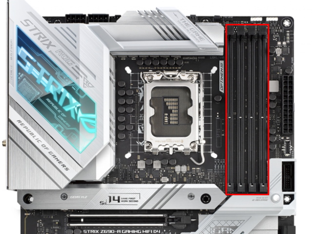
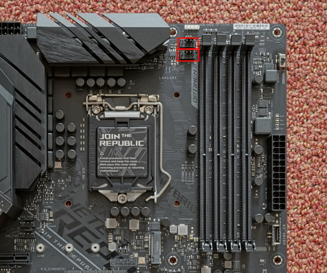
Modern memory slots look like the one we have featured above (marked in red) and have one side with a clip that is used to hold the memory stick in place. The other side is usually ridged to hold the stick in place but allows the memory stick to be pressed into the slot without the need to have a second clip like the ones that used to be in older motherboards (shown below).

In the example above, the CPU that fits on this motherboard has two memory controllers. And each one handles 2 sticks of memory, hence, there are 4 sockets in total. Also, you can see that the memory sockets are colored in way to let you know which ones are managed by which controller. They are commonly called memory channels, so channel 1 (colored blue) handles two of these slots and channel 2 (colored grey) handles the other two. The channel closer to the CPU socket is usually channel 1 and is where you should install your first stick of memory.
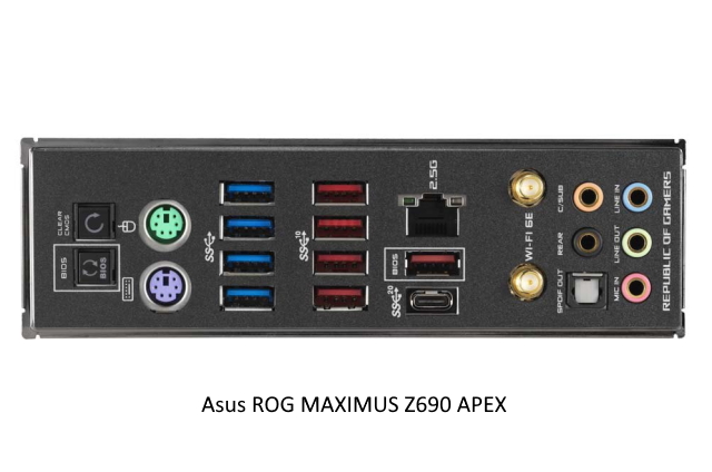
Power Connectors
To provide the voltage and current required to run the motherboard and the many devices attached to it, the computer’s power supply unit (PSU) has a number of standard connectors for this purpose. The 2 main power connectors that are available on all modern motherboards, much like the Z690 shown below are the 24-pin and the 8-pin connectors.
The main one is the 24-pin ATX connector that is located on the right side of the motherboard. While the connector has 24 pins, depending on the computer, they can run using anywhere from 20-pins to little as 11- pins in small prebuilt towers.

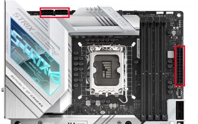
The 8-pin, on the other hand, exclusively powers the CPU and is usually located on the top left of the motherboard. The 8-pin connection may be a 4+4 pin, though some high-end CPUs even have an 8+4 pin connector.


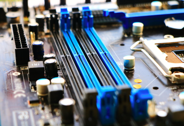
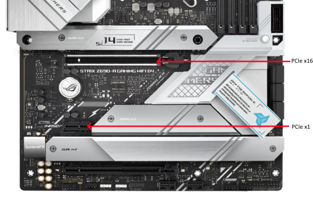
PCI-Express Slots
The PCIe Express sockets are long RAM-like connectors right below the CPU socket. Every desktop motherboard has at least one PCIe slot and can be used to add other PC components to the system like GPUs, Wi-Fi cards, or PCIe SSD (Solid state drive) add-on cards. The PCIe is essentially an interface standard that is used to connect these high-speed components to the CPU.

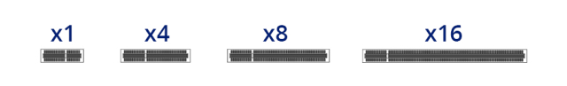
The types of PCIe slots available in your PC will depend on the motherboard you buy. But the main physical configurations that they come in are: x1, x4, x16, and x32. The number after the x denotes how many lanes that PCIe slot has – the higher the number, the more speed the connection can achieve. On the current PCIe gen 5 standard available in the latest Intel processors, bandwidth can go up to 120 GB/s in a 16x configuration.

Cards and slots can be mixed and matched despite the number of lanes indicated by each component, with data bandwidth determined by the slower part. For example, if you have a PCIe x16 slot on your motherboard, you can connect a PCIe x1 card. Here, your bandwidth will be capped by the card’s single available lane, which is one bit per cycle. Similarly, if you put a PCIe x8 card into a slot that is either x1 or x4, data will travel in 1/8 or half bandwidth compared to what it would have if inserted in the default x8 slot.
So what are the common use cases of these PCIe sockets? As we have already mentioned, the PCIe socket is a remarkably flexible platform that can be filled with numerous expansion cards.
The most common use cases for different slots are as follow:
- x16 lane = Graphics card
- x4 lanes = solid state drives (SSDs), capture cards
- x1 lane = sound cards, USB adapters


You can see the difference between the connectors in the image above. The graphics card sports the longer x16 lane standard compared to the storage card’s tiny 1-lane setup. Since the storage card has far less data to transfer than the graphics card, it doesn’t need all those extra lanes.
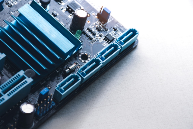
SATA and M.2 Slots
Different motherboard configurations place SATA ports differently, but you can always note it, given its unique plug and onboard labeling. The small kink on the plug determines its orientation. In our reference motherboard here, the SATA ports are located on the right side of the motherboard.
SATA ports were the primary data transfer ports for years and were used with all kinds of different hardware from CD ROMs to Expansion ports and hard drives. They are still very common in most computer builds, and to this day, form the backbone of computer storage in most motherboards.
The standard that has taken the storage standard baton from SATA is the M.2 slot. Formerly known as the Next Generation Form Factor, the M.2 standard has taken the PC world by storm. And only in a short span, it has become the dominant storage standard in both desktop and laptop PCs. The reason why it has become so popular is multifarious. The slot is not only tiny, but is also flexible as it can interface with both older SATA 3.0 (still a popular standard), PCIe 3.0 (the default for newer graphics and expansion cards), and even USB 3.0. Most new motherboards at least have one M.2 slot, but some high-end ones can have up to 4 slots.

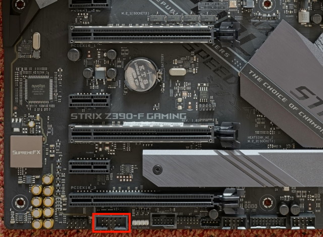
Motherboard Fan Headers
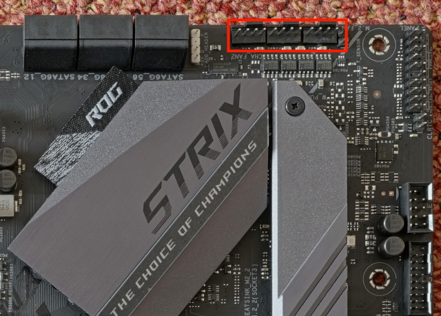
Next up are the motherboard fan headers. These connections are either three or four-pin modules that are usually present right above the CPU socket. They are, unsurprisingly, used to power the cooling fans inside your computer, although you can use them to power other components like water pumps and RGB lights. One could essentially think of these as mini 12V power connectors designed originally for fans, only now they have a variety of uses.

In the picture above, we can see that the CPU fan header is present on the top-right section of the CPU socket. It is labelled CPU_FAN and CPU_OPT. There are other fan headers peppered throughout the motherboard and are usually labelled as SYS_FAN.
Now, the only real distinguishing feature between the CPU fan header and other fan headers is that the CPU fan has an inbuilt failsafe to protect your CPU from damage, if there’s no fan plugged into the CPU fan header then the computer will not boot. For chassis fans, you should use the SYS_FAN header, as they are located all over the motherboard making cable management easier depending on where your fan is located.

Note: CPU_OPT stands for CPU Optional.This header is meant to power the secondary CPU fan, though people often use it for powering AIO or liquid cooling systems too.
Another thing that you have to keep in mind regarding fan headers is that there is a difference between 3- and 4-pin headers. The 4 pin fan headers supports pulse width modulation, which works like a switch, turning on and off while controlling the level of power delivered to the fan or pump. This allows fans with 4 pin headers to achieve seamless speed control, which is difficult to achieve in 3 pin (DC) fans.
VRM and MOSFET
The next part of the motherboard that we will be looking at is not a connection or a port, but rather an important part of the motherboard that makes it’s functioning possible – VRMs. Now, VRM is a term that is discussed a great deal in the overclocking community, and if you are into that, you might have come across it.
So what is a VRM? The term stands for Voltage regulator module, and it describes an electronic channel that regulates and modifies the main voltage it receives from the power supply. On current-gen power supplies and motherboards, it means taking a 12V current and converting it into either 1V for the GPU or 1.4V for the CPU. The process of conversion is complicated, but the principle that voltage regulation circuits rely on is the ability to reduce the average output voltage of the circuit by switching the input voltage off and on.
That means if you have a 12 V output, and you switch it off and on for equal parts, the average voltage would be 6 V. This rapid switching of voltage is done by a metal oxide semiconductor field effect transistor (or MOSFET) circuit.
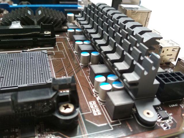
Since our reference motherboard does not have visible VRM modules, we have used a different image to showcase the same. Here, you can clearly see the MOSFET transistors and the capacitors that are used to convert the voltage. Since they deal with high amount of current they do tend to get hot, and this is the main reason why they are usually accompanied by a slew of heatsinks.
Motherboard Rear I/O Ports
Now, we will look at the motherboard’s main I/O panel, which is almost always located in the back. This is the area where you will connect most of your peripherals, including the keyboard, mouse, displays, etc. The arrangement and the number of ports might vary depending on your motherboard’s model, but since we’re using a high-end motherboard for reference, it should cover most of the ports currently present on the latest generation of motherboards.

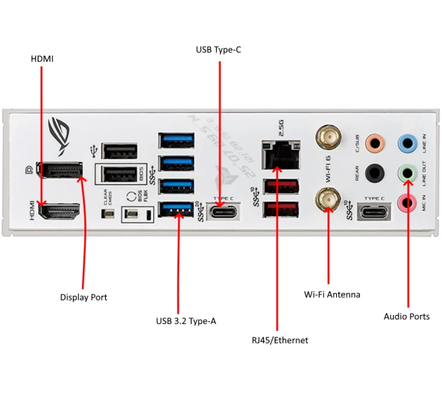
- USB Ports
The first set of ports on the rear I/O that we will be looking at are the USB ports, which come in a variety of colors and at least two shapes. Notice the standard rectangular USB-A ports; different versions are signified by the color of the port, but USB ports and most devices are backwards compatible.
The USB Type-C port – an oval-shaped port located on the right of blue USB ports – is another type of USB that’s available on most modern motherboards. While USB-C ports are newer, they function identically to its more common brethren, but is able to transfer data at greater speeds and is also able to transmit higher levels of power.
USB Colors Features Black USB 2.0 with speeds up to 480 Mbps Blue USB 3.0 with speeds up to 5 Gbps Teal USB 3.1/3.2 with speeds up to 20 Gbps Red USB 3.2 with speeds up to 10 Gbps, Always-on charging port
- HDMI/ Display Port
Looking towards the left of the panel, we have the video ports. Pictured here are two of the more modern video connections, HDMI below with Display Port or DP above. While most motherboards come with video ports, many higher-end CPUs no longer come with integrated graphics (AMD for example), relying instead on a dedicated video card and its display ports to power the displays.
- RJ45 Ethernet port
Next, we see the Ethernet port. This is where the network cable would plug in to your computer. Virtually all motherboards will have one of these RJ45 Ethernet ports as desktops typically rely on a wired connection to the internet. Ethernet still delivers the best network speeds and connection stability.
The current industry standard for a decent ethernet connection is a Gigabit port, but some higher-end motherboards can also come with a 2.5 Gigabit ethernet or 10-Gigabit ethernet port at the ultra high-end.
- Wireless Connectivity
Right next to the RJ45 port, we have the Wi-Fi and Bluetooth antennas. These give your computer the ability to connect to a wireless network without having to install any additional hardware, like a PCIe Wi-Fi card. Now, Wi-Fi on motherboards can be expensive, and this is the reason why many budget motherboards don’t have this feature.
- Audio ports
For our last item on the rear panel, we see the audio ports. The reference board that we are using has several connectors, but most of the time, it comes down to what your sound setup is. Almost all motherboards we find on the market today use the same standard color scheme for audio ports. The color green is usually used for audio-out (speakers/ headphones), and red or pink is for audio-in (microphones). There are also ports (peach and black) for additional hardware like subwoofers or extra speakers.
Motherboard Front I/O Ports
The last connectors we will be looking at are the ones that are used for controlling the basic operation of your motherboard and attaching additional devices or extensions. They are called Front Panel Connectors and are usually a block of connectors on a motherboard that controls the power on, power reset, and the LED light indicators of your PC case.
These connectors, for the most part, are located on the bottom right of the motherboard. The cables that connect to these pins are usually included with the PC case.

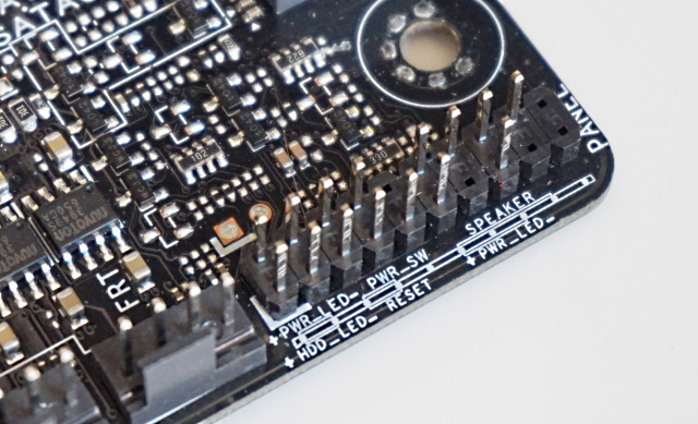
There are five primary connections that almost all the front panel headers have:
- Power Switch Pins (abbreviated as PWR or simply PW) are 2 pins that connect to the Power Button cable coming from the PC case.
- Reset Switch Pins are 2 pins that connect to the reset switch on the PC case.
- Power LED Pins are 3 pins that connect to the LED light on the PC case that indicates whether the PC is on, off, or in sleep mode.
- Hard Disk LED Pins are 2 pins that indicate the activity of the hard disk by flashing repeatedly.
- Speaker Pins are 4 pins for the beep code speaker. Many PC Cases come with a beep code speaker.
Outdated Motherboard Ports
As we have previously discussed, the motherboard is always evolving, gaining new standards and connections. Over the years, some of the most beloved ports have gone the way of the Dodo and have been replaced by newer, faster standards. But at the same time, they haven’t been forgotten. For many in the PC community, these ports live on in their hearts, and if you are lucky, you might still be able to find these ports in newer hardware.
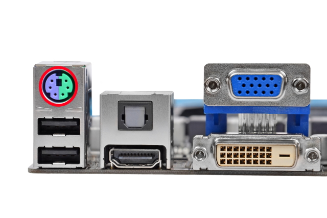
PS/2 Port
One of the most beloved of ports, and one that has seen a great decline in popularity and viability is the PS/2 port. It has been now been superseded by USB for several years, but for some reason, refuses to die. Some of the most advanced gaming motherboards like the Asus PRIME Z690-P still come with dual PS/2 ports.
So why is the PS/2 port so revered? The answer lies in the concept of polling rate, or the number of times a peripheral is updated (polling rate) by the computer to see if they’re idle, moving, or doing something. Over USB, the base polling rate can range anywhere from 250 Hz to 1000 Hz.
The PS/2 peripherals, on the other hand, don’t have a polling limit, as they are able to send an uninterrupted signal to the CPU whenever they are doing something. If you move your mouse or click something, your mouse will directly communicate with the CPU to register the action, rather than waiting for the computer to notice. This means, in most cases, there is less latency than with a similar USB peripheral because it’s not polling but actively interacting with your computer.
They also have other advantages. In the case of keyboards, PS/2 opens the possibility of true N-key rollover, meaning you can press down on however many keys you want, and they will all register. If you reboot into your BIOS, there’s a chance your USB peripherals will not be recognized, whereas you won’t have that issue with PS/2 peripherals since they’re all universally compatible.
Serial Port
Another one of the ports, that has died out over the years is the serial port, which was an asynchronous port on the motherboard that used to connect many serial devices of the time (80s and 90s). Just like the PS/2 port, serial ports have largely been replaced by USB these days.
These days serial ports are usually identified on most compatible motherboards as the COM (communications) port. For example, a mouse might connect to COM1 and a modem to COM2. The picture below shows the serial connector on a modern motherboard.

Some uses of the serial port in the past are as under:
- Mouse: One of the most commonly used devices that you can connect with the serial port was the mouse. It was particularly popular with computers that had no PS/2 or USB port.
- Modem: Another frequently used device for serial ports was the modem. The port provided an easy upgrade for people who wanted to add an external modem to their setup without upgrading their hardware.
- Network: The serial port was essentially a way to transmit data. Thus, one of its original strength was that it allowed two computers to connect together and allow files to be transferred between the two.
- Printer: Today, USB and other proprietary connections are used by printing companies for data transfer. However, Serial ports were frequently used in older printers and plotters.
What are Chipsets in Motherboards?
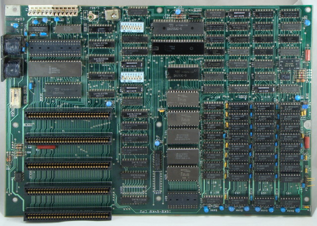
If you come across motherboards from a decade ago and observe its layout, you would spot two additional chips next to the CPU. Together, these chips were called a motherboard’s chipset, and individually were referred to as the Northbridge (NB) and the Southbridge (SB) chips. They were responsible for handling everything from system memory (Northbridge), graphics card, and storage instructions in old motherboards. They essentially acted as the computer’s minor brain.

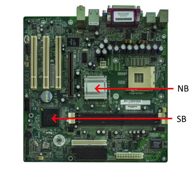
The above image is of an old Intel motherboard, which clearly shows the NB/SB chips – one is hidden under an aluminum heatsink, but the one further from the CPU is not. The one which is closest to the CPU is the Northbridge, while the one further away is the Southbridge. This configuration with a separate northbridge and southbridge was so successful that it remained an industry standard for years.
But as processor design started to integrate more functions onto fewer components, the memory controller (northbridge), which handled transmissions between the processor and memory was moved onto the processor die by AMD and Intel starting from 2010. The companies argued that having the memory controller integrated into the CPU die not only saved space on the motherboard but was also one of the best ways to reduce latency from the CPU to memory.
The Southbridge chipset, though, has remained a separate entity and is likely to be so for the foreseeable future. Also, both the major CPU manufacturers – AMD and Intel – have stopped calling it the southbridge and instead just refer to it as the chipset. Intel has gone further in the recent years and named it the PCH, or platform controller hub. AMD, on the other hand, has named it the Fusion controller.
Chipsets and Features
So what does a chipset do in modern motherboards? This chip is essentially an advanced controller, one which handles multiple types of connections like USB, SATA, or PCIe. The chipset acts as a secondary brain for your computer and has been delegated the work to make sure high-speed components like drives and USB devices can efficient communicate with the CPU.
The quality of the chipset, thus, determines how many high-speed components or USB devices your motherboard can support. Moreover, the chipset model also decide how much a motherboard costs. As with most hardware, newer means better and typically more expensive, and chipsets are no different.
So which chipset should I buy? Now, this is where things get complicated, as comparing motherboard specs and motherboard chipsets can feel difficult. Again, like most things in tech, chipsets (and motherboards) carry cryptic names featuring just letters and numbers. If you’re not familiar with chipset naming schemes, the nomenclature is unlikely to make sense.
In both AMD and Intel’s case, keep in mind the single letter followed by a few numbers, as they use a similar naming style. However, they do not use the same letters and the performance categories do differ. In Intel’s case, most modern chipsets use the letter H,B,Q,Z and W, such as the Intel H610 or Z690. The Z line of motherboards are usually the high-performance ones, while the H line is the budget option. AMD, on the other hand, use A,B and X with motherboard models such as X570 or B550.
Below we have a comparison between the high-end Z690 chipset and the entry-level H610, which are both Intel 12th-Gen chipsets. The idea of this comparative analysis is to showcase the huge feature differences that can exist between different motherboards.
Key Features Intel Z690 Intel H610 CPU overclocking support Yes No Max memory slots 4 2 USB ports 14 (includes 3.2 USB) 10 (does not include 3.2 USB) PCI-E Lanes 32 16 Max SATA ports 8 4
There are also some intangible differences between the motherboard chipsets which aren’t apparent on the specs sheet. More expensive motherboards usually have better quality components. This is fairly evident when we look at the common failure point on inexpensive motherboards, which are usually cheap capacitors.
Furthermore, expensive motherboards often have more layers in the actual PCB, which makes them more resistant to heat and stress. This makes more expensive motherboards a better choice if you intend to put high performance components that get hot or are power hungry.
Frequently Asked Questions (FAQ)
Which motherboard should I get?
If you’re in the market for a new PC, one of the most important decisions you’ll make is to choose on which motherboard to buy. And since motherboard prices and specifications vary tremendously, making the right decision can be a bit tricky. So while, a full buyer’s guide is out of the confines of this article, there some things which you can keep in your mind while purchasing.
The two most important factors, which you should keep in mind are the features and the form-factor you want for you build. For example, if you want Thunderbolt support in your next PC build, you will probably have to go with an Intel motherboard. Few select AMD motherboards support the technology but it’s mostly found on Intel boards, as Intel helped create it. Need the best multicore performance? You will want AMD here. Threadripper or Ryzen 5000 chips have a significant core count advantage over existing Intel HEDT choices and so on.
This further applies to the question of which chipset to buy? Depending on your use case, you should figure out what are the features you really need. Need lots of USB or audio connections for your audio setup? Buy a chipset like the Z690 that has more USB slots. How about HDMI integrated into the motherboard? Look for a motherboard model that supports this feature. We recommend that if you’re buying a motherboard, do have a look at its spec sheets, as it might just help in making your decision a lot easier.
Will my new Motherboard support the newest Intel/ AMD CPUs?
With new processors coming in every year, knowing which motherboard will support the newest Intel or AMD chips can be difficult. This why we have listed all the latest processors and chipsets that are currently popular in the PC marketplace. For a detailed breakdown of all Intel chips and supported processors, you can have a look here.
Starting off with Intel, here are all the Intel 12th Gen chips that will slot into the LGA 1700 socket:
Core i3 Core i5 Core i7 Core i9 Others Core i3-12300 Core i5-12600K Core i7-12700K Core i9-12900F Pentium Gold G7400 Core i3-12300T Core i5-12600 Core i7-12700KF Core i9-12900KF Pentium Gold G4700T Core i3-12100 Core i5-12500 Core i7-12700 Core i9-12900 Pentium Gold G6900 Core i3-12100F Core i5-12400 Core i7-12700F Core i9-1290F Pentium Gold G6900T Core i5-12400F Core i7-12700T Core i9-12900 T
However, if you’re looking to upgrade your chip in an older Intel socket, remember that unlike the LGA 1700, which is only compatible with the new 12th-Gen chips, older motherboard sockets support anywhere from 2 to 3 generations of chips. This means that if you’re on a 10th-Gen chip on the LGA 1200 board, there are high chances that you will be able to upgrade to a 11th gen chip relatively easily. To check what motherboard you have, follow our guide linked here.
In the case of AMD, compatibility is much better as even the Ryzen 5000-series chips run on the same AM4 platform. So most chips till the 3000-series will run without a problem on older chipsets. However, for newer 5000-series chips, the list of compatible motherboards have shrunk. But even so, most 300 and 400 series should work with a BIOS update.
Note: Videocardz, an online website, has a compilation of BOIS updates of all supported Ryzen-5000 series motherboard. So if you have a old motherboard and want to know if it’s compatible, have a look here. Also, learn how to enter BIOS/UEFI on Windows 11 using this dedicated guide.
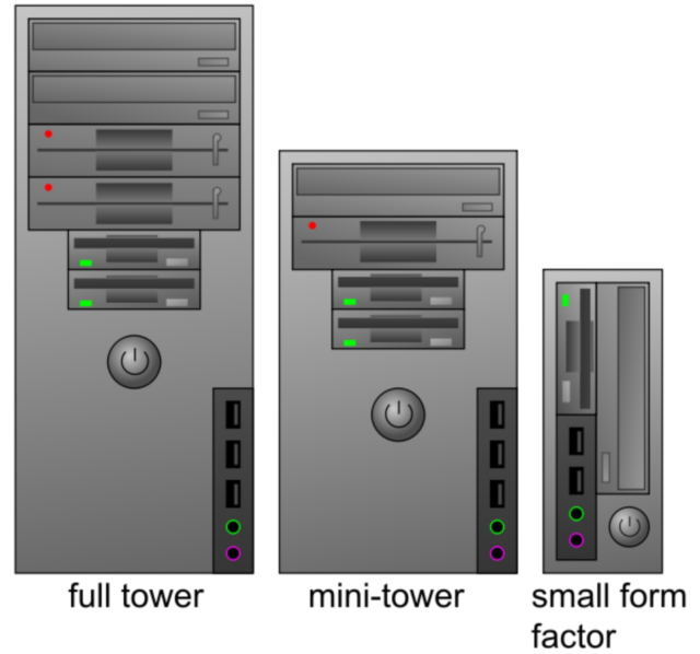
What PC cases are compatible with my Motherboard?
The simple answer to this question is – it depends. There are certain PC cases that can fit all types of standard motherboards, but then there are a few that do not. To understand this better, we should have a look the different PC case sizes. There are essentially four common sizes for PC cases:
- Small Form Factor
- Mini Tower
- Mid Tower
- Full Tower
There are additional sizes such as Ultra Tower and HTPC, but they serve a specialized purpose and are generally not intended for typical commercial home, office, or gaming PC needs.

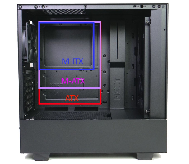
Each of these case sizes have recommended motherboard sizes that they can accommodate. For example, a small form factor PC is the best use case scenario for Mini-ITX motherboards that we discussed earlier. But it does not mean all cases are exclusive to specific motherboard sizes.
A mid-tower PC case, particularly intended for ATX motherboards, can fit the smaller sizes M-ATX and mini-ITX motherboards. So yeah, the recommended case sizes are just a kind of guideline, which tell you the best case scenario for the given motherboard.They are not to be read as gospel. So if you already have a M-ATX board and you want to change you PC case, you should have a range of choices for new case, as you can use either small factor cases or even the larger Mid-tower cases.

Dissecting the Motherboard Structure
And we are done! We have successfully looked at every major component on a modern motherboard in 2022. We know it wasn’t the easiest deconstruction to follow, but as we all know motherboards are big, complex circuit boards that are packed with cutting-edge technology, so the detailed explanations. There is so much history and technology that is etched in every corner of the motherboard. But at the same time, we often forget about them as they sit in our PC case.
We hope that you have come out of this exercise with a bit more knowledge about the motherboard and now have a greater appreciation of its functions. We have also tried to answer some of the most common questions that people have when choosing a new motherboard above. But if you have any more doubts, do let us know in the comment section below.


