
If you have ever been interested in the cult-like activity that is CPU overclocking, one of the terms that you would have come across a great deal is VRM. The term is ubiquitous in the PC community, but hardly anyone inside or outside the community actually knows how it works. VRM is one of those things that people know is crucial to the operation of their PCs but seems so mysterious that any further investigation would be too cumbersome. This is why we have done the required research and come up with this explainer to tell you what is VRM on the motherboard, how it works, and how it affects your CPU performance.
Motherboard VRM: Explained (2022)
In this article, we will be exploring everything there is to know about VRMs and tell you why they are so important. We will see how VRM’s task, while simple, is an essential one, as it is key to ensuring the stability of the system. In other words, it’s well worth knowing more about VRM and how it operates.
Furthermore, we will also be looking at how one can differentiate between a good-quality VRM and a bad one. The idea behind that would be to create a basic idea of what constitutes a good VRM configuration, so you know what to look for the next time you buy a motherboard.
What Does VRM Stand For?
Before we do a deep dive into how the VRM works, it is essential to understand what it is and what the term stands for. The term stands for “voltage regulator module”, and it describes an electronic circuit that regulates and converts voltages to meet the requirements of the CPU, memory, and GPU. It might help one to think of VRMs as kind of like a mini power supply, just like your actual main computer power supply that takes 120 or 240 volts from the wall and bumps it down to 12 volts of DC current.
The motherboard VRM in a sense does just that, but for a second time. It takes the 12-volt (DC) output of the power supply and converts it to typically around 1V for a GPU or 1.4 V for a CPU. The other important task of the VRM is to supply this voltage steadily, without surges and drops, as it can affect the stability of the entire computer.


In the above image, you can see the architecture of the VRM in a modern motherboard. It includes three primary elements: MOSFETs, Chokes, and Capacitors. Most of these are usually located under heatsinks that surround your CPU socket and are quite hard to spot. These core components are accompanied by diodes and resistors, which ensure that the electric current that arrives at these components does not exceed certain values.
How Do Motherboard VRMs Work?
The key principle on which voltage regulation circuits rely is the ability to reduce the average output voltage of a circuit by switching an input voltage on and off. So, for example, if you have a 12V DC input from your power supply, and you switch it on and off for an equal period of time, the average voltage would become 6V DC.
But to achieve a relatively stable average voltage, this needs to happen several hundred times a second. The switching in almost all of the cases is achieved via a relatively simple metal oxide semiconductor field effect transistor (MOSFET) circuit. But as we will see in the next section, the MOSFET doesn’t work alone, but rather in tandem with other units like chokes, capacitors, and PWM controllers to give the CPU the most stable power possible.
Components of VRM in Motherboard
MOSFETs
The first component that we will look at is the MOSFET, which is essentially an insulated gate, a kind of switch that is used to amplify or minimize electronic signals. What it does in practice is regulate the passing current, depending on the signal and value sent by the PWM controller chip, which is responsible for managing the power phases and balancing the signals (more on it later).
To better illustrate this process, we can look at the diagram below. A basic VRM circuit consists of two MOSFETs, which in this situation are basically just switches, an inductor, and a diode.
The design of VRM MOSFETs can vary, but they all have the same function, so we think it’s not necessary for us to go in-depth and start explaining some advanced electrical engineering. However, if you want a more detailed discussion of each component’s function, head to WikiChip’s VRM explainer page. The important bit you need to know is that the voltage conversion starts at the MOSFET, and it is here that most of the workload happens.


But to explain it briefly, the VRM circuit uses two MOSFET switches to control the amount of voltage that passes to the CPU. When the first switch (high-side MOSFET) is closed, the voltage at the input of the inductor becomes 12V. This causes the current to start flowing through the choke, which is essentially a coil of wire around a magnetic core – slowly raising the output voltage.
Then, once the desired voltage for the CPU or GPU is reached, the switch is closed, which means the input to the choke becomes zero. As the electrical supply to the choke drops, the magnetic charge around it dissipates, inducing a voltage in the opposite direction (so it’s adding to the output voltage rather than canceling it), which slowly drops off over time. This process when repeated several dozen times a second gives us a relatively steady increase and decrease in voltage (as seen in the voltage figure).


The other thing that we have to keep in mind about MOSFETS is that every single time it switches on or off, it generates heat, which can be above about 150 degrees Celsius. That means as you push MOSFETs more and more to their limit, they tend to heat up a lot. Does this heat matter? Simply put, it does.
If the VRM MOSFETs get too hot, it affects the resistance of the semiconductor, which leads to a drop in efficiency, and from there, it’s a never-ending loop that will only generate more heat. And this is the key reason why most MOSFETs in modern motherboards are covered by cooling solutions like heatsinks or miniature fans.
Chokes
The next part of the VRMs that we will be looking at is called Chokes. These are cubic-shaped (although not always) inductors normally made of metal, which are responsible for converting alternating current (AC) signals into lower frequencies or direct current (DC) in order to stabilize the voltage that comes out of the MOSFET. What does this mean?
Essentially, a choke takes the high-frequency power (12V) coming in from the PWM and turns it into a stable frequency (1.2-1.4V), so it becomes usable by the CPU and other components. So, in essence, it serves two functions. First, to store and filter the power, and secondly, to control the overall quality of the power.


Since chokes play an important role in the quality of power supplied to the motherboard, they are essential in deciding the overclocking ability. The better the chokes, the higher the motherboard’s capability to withstand overclocking. Furthermore, each choke on a motherboard also represents a power phase. And as a general rule of thumb, the higher the number of phases on a motherboard, the more stable the voltage (more on this later).
Capacitors
The last core analog component of the VRM that we will be exploring is the Capacitor. It is a common electrical component used in many electronic devices to store energy in an electric field, and when required, it can discharge this energy into the circuit they are connected to. It acts like a battery in a sense, but has higher storage capacity for its ability to rapidly output all its energy.


For a VRM and its corresponding power phases, it serves the same purpose. The capacitors have two main functions in the functioning of the VRM. The first is to accumulate electric current, and the second is to store and prevent voltage surges and reduce ripples in the electronic circuit. The idea is to store the current received from the choke and supply the right amount of power required by the CPU, the rest is discharged or released via the ground.
This means that the capacitor is not only an important part of the VRM but rather an existential necessity. That’s why, for any VRM to be considered good, it most certainly would have to make use of high-standard and high-quality capacitors. Usually, high-quality capacitors are branded as Solid Capacitors, Hi-C Capacitors, and more. In the modern generation of motherboards, solid-state capacitors are the dominant form of capacitors and have mostly supplanted electrolytic ones.
But this wasn’t always the case. In the late 1990s and early 2000s, a lot of motherboards, particularly, from Taiwanese manufacturers saw higher-than-expected failure rates of non-solid capacitors. This was largely due to electrolyte composition that caused corrosion, leading to high levels of gas generation, which often caused the capacitors to explode. This was known as the capacitor plague of the early 2000s and is infamous in the PC community. While the problem was a very complicated one, which had a whole host of controversies from industrial espionage to corruption, its larger implication was that the industry gradually moved from alkaline capacitors to solid-state ones.
PWM Controller
Now that we have discussed the core analog components of the VRMs, it’s now time to move on to the part of the circuit that controls the electricity flow called the PWM (pulse width modulation) controller. This controller provides the PWM pulses, which are then fed into the analog part of the circuit – MOSFETs, Chokes, etc.


These PWM controllers, however, aren’t simple devices that just fire out a fixed pulse. Instead, they are rather complex integrated circuits themselves. Some controllers, particularly high-end ones, have multiple phase control systems, and they also take care of another crucial function of the VRM, i.e. monitoring. Moreover, since the voltage of the CPU or GPU is never truly constant, the chip does a lot of work to regularly reduce or increase the required power in order to be more efficient.
So how does it know how much power to send? Simply put, it does this by forming a feedback loop between the CPU and the PWM. The PWM controller takes the reference voltage (VREF) of the CPU, found in the motherboard’s BIOS settings, and constantly feeds it into the VRM. This voltage is then measured with the current voltage, and if there is a difference between the VREF and the actual voltage, the PWM controller modifies the signal to bring the output voltage back in line.
This process was, till a decade ago, mainly done by analog PWMs, but for the most part, have mostly been replaced by digital PWMs today. The advantage of digital PWMs is that it opens up the microcontroller to consider a much greater range of other variables and parameters in its voltage correction calculations. These could be temperature sensors, BIOS settings, and other stored values. The downside to digital PWM controllers is they are more expensive and complex to configure. Modern motherboards almost exclusively use digital PWMs for CPU and memory power delivery, but analog PWMs are sometimes used for less critical parts of a board.
What Are Power Phases of a Motherboard?
Since the turning on and off of the electrical signal by the MOSFET is normally done several hundred times per second, the voltage can fluctuate more than the CPU can tolerate. And since it is already operating at such a high speed, it isn’t practical to try switching a whole lot faster than that. So in the pursuit of better stability, what we need is not faster MOSFETs but more of them in quantity.

A single VRM circuit can be effective enough for certain applications, but to ensure as smooth a voltage delivery as possible, you can have multiple VRMs in parallel, creating what we have already mentioned – a multi-phase VRM (the image above represents a multi-phase VRM). How does this work?
From the above diagram, you can see that if each phase of the VRM is staggered just in the right way, the phases distribute the energy load over a wider number of components. Not only does this provide the CPU or GPU with smoother power, as the time between power pulses can be reduced, but also helps in reducing heat production and stress on components.
You will often see motherboard manufacturers advertise high numbers of phases in an A+B format, like 8+3 or 6+2. So, what does this mean? In theory, it’s simple enough. The first number is the number of phases dedicated to the CPU, while the second is the number of phases dedicated to other parts of the motherboard like memory.


It is in this context that you might be tempted to think that more phases equal smoother power delivery. This is true to a certain point. For example, entry-level boards usually have three or four-phase CPU power, while higher-quality boards can have six to eight. However, where it gets complicated is when motherboard manufacturers say a board has, for instance, a 16+2 design, but may in fact be using a doubler and only have a true 8-phase setup.


A doubler allows you to multiply the benefit of existing phases without including additional phases on the board. The net result is a similar reduction in overall load and heat generation as a normal multi-phase circuit, discussed above, but only with a voltage ripple reduction of half the circuits. That said, though, the overall benefit of larger numbers of phases is rather diminishing. So you will get a more reliable motherboard in a sense, but since the power delivery hardware is essentially similar to a lower phase one, it will probably not overclock as well.
Furthermore, multiple phases also have another benefit. Say you have a CPU that requires 100 amperes to run with a single phase. So, all 100 amperes would have to go directly through those components. But with two phases, only 50A goes through each phase, which means that components with a lower rating can be used, and these components are usually cheaper. This allows manufacturers to make 4-phase VRMs at a much cheaper rate than, let’s say, if they had to make a 2-phase VRM with better quality components.
Can the Quality of VRM Impact CPU Performance?
The question that most computer users have about VRMs is – How does VRM affect my system’s performance? Truth be told, the quality of VRM will not have the impact of, for example, getting a new $600 graphics card on your system. But the quality of your VRMs can make a huge difference when it comes to the longevity and stability of your system.
This is because cheaply-made VRMs can start to fail over time, and it can lead to system instability and even crashes at stock speeds. Furthermore, a poor-quality VRM can mess up the power delivery of your motherboard to the point where it could damage other expensive components.
And finally, if you ever want to start overclocking on a bad-quality motherboard, say goodbye to that dream, since you won’t get far with a poorly designed VRM module. Why? Because as you push your PC during overclocking, you require high-level control when it comes to voltages, which can only be provided by higher-quality VRMs.
How Can You Tell If Your VRM Is up to the Task?
You must be looking at your motherboard and asking yourself, how do I make sure that my VRM is up to the task of overclocking and won’t simultaneously combust when I push the voltages a little bit? Deciphering a motherboard’s VRMs can be a bit tricky, but one of the easiest things you can do is just count the number of chokes you see on the motherboard.
As we have already mentioned, each choke on your motherboard corresponds to one power phase, and usually, all but one or two of these chokes around the CPU socket are reserved for CPU cores. This means that if you have a motherboard with many chokes, it probably has a number of phases that can split the overclocked voltage, lightening the load on each phase.
So if you have a motherboard with three or four phases for the CPU, it’s probably an entry-level board. That means it’s probably not suited for ultra-high-performance chips. But if you have six, eight, or even more phases in your motherboard, it’s probably a high-end board that should have no problem keeping your system stable even under load.

Furthermore, it’s also a good idea to see if your motherboard comes equipped with solid-state capacitors or cheap liquid-based capacitors that contain conducting liquid. Liquid capacitors (electrolytic) can cause problems to the system if they are not constructed properly. And even if they are made correctly, they have a high chance to bulge, rupture, or even explode over time.
Where it gets complicated is when manufacturers say your motherboard has, for instance, a 16+2 design, but the board may in fact be using doublers and only has a true 8-phase setup. Finding out the exact setup can take a bit of sleuthing, either searching online sources that have already done the digging or looking up the PWM chips and finding out how many phases are actually rated to handle the load.
If the chip only has four or eight phases, and the board claims 16, clearly some doubling is going on. For most people, it won’t be a concern one way or the other, but if you are looking for a serious competitive advantage in overclocking, a robust VRM setup is crucial.
So should you be worried if your motherboard has only 4 phases? Well, it depends on which processor you are using. If it is a modern-day mid-range CPU like an Intel Core-i3/ i5 (8th-Gen or later) or an AMD Ryzen processor, it should be just fine. CPUs have gotten to a point where they can do so much more with much less power. And as the industry is moving towards more power-efficient chips, the days of the high-numbered power phases are coming to an end. But if you are someone who wants to upgrade to a high-performance/ overclockable chip, it would be ideal if your motherboard has a higher number of power phases.
Why Good VRMs Are Required for Overclocking?
While the amount of VRMs, their size, and the number of power phases supported by your motherboard is an important factor, it does not have a huge impact on your day-to-day performance. It does, however, matter for enthusiasts, gamers, and other professionals who want to overclock your CPU. This is because overclocking directly puts a burden on the VRM, as increasing the voltage is essential when it comes to hardware overclocking. As more and more voltage is run through the system, regulating it becomes an increasingly harder task.

This is the situation where everything from the number of phases to the size of your heatsink and the quality of capacitors starts to matter. And it is for this reason that high-level overclocking is reserved for only the best of motherboards. These motherboards not only have a high number of power phases but are also built with premium sub-components like solid-state capacitors that have the capability to withstand a high amount of voltage and current. Moreover, these motherboards are also armed to the teeth with good cooling setups, as some even have active cooling, which includes small fans or even liquid cooling blocks.
VRMs: Frequently Asked Questions
How to Find If My Motherboard Has Solid Capacitors? What Are Its Advantages?
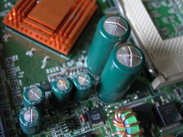
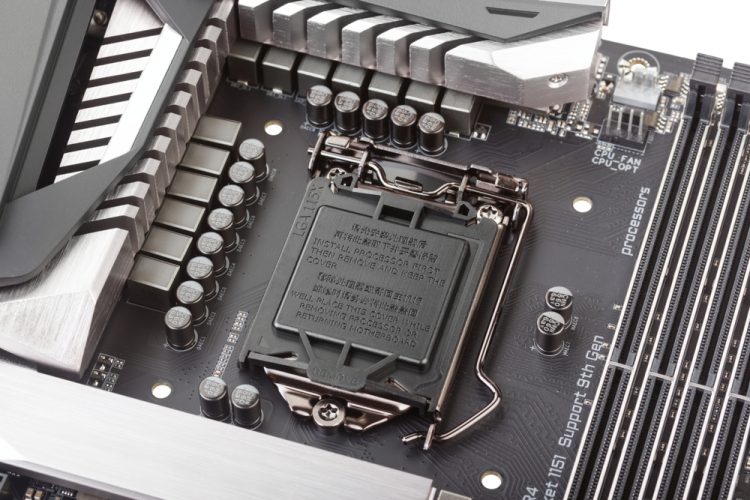
The easiest method to see which capacitors the motherboard on your PC has is to physically look at them. Visually, the capacitors look very different as they both have fundamental designs. The solid-state capacitors are usually smaller in size in comparison to electrolytic capacitors.
You can easily spot the difference in the comparative image below, where the motherboard in the first image was designed using only solid-state capacitors, and the motherboard in the latter image uses the more common and less expensive electrolytic capacitors.


Solid capacitors and electrolytic capacitors store electricity and discharge it when needed. The difference, however, is that solid capacitors contain a solid organic polymer, while electrolytic capacitors use a common liquid electrolyte, hence, the difference in names.
So how does this affect the capacitor’s performance? In terms of lifespan, solid capacitors last longer than electrolytic capacitors, especially at lower working temperatures. In some cases, solid-state capacitors can last more than 6 times longer than electrolytic ones. If one were to convert this difference in actual years, the solid capacitor would last approximately 23 years, while the electrolytic capacitor would die after only three years.
Furthermore, solid capacitors also have a higher tolerance not only for higher temperatures, but they also perform better with higher frequencies and higher current than electrolytic capacitors. And lastly, unlike their counterparts, the solid capacitors have no chance of exploding, as there are no liquid components in their body. All of this, in combination, makes them much more suited to extreme stress operations, which can include overclocked setups or workstations.
Which Motherboard Should I Get for Overclocking?


Buying a motherboard is already a complex decision as the market is filled with different socket types and form factors. It is further made more complicated if you intend to buy a good motherboard for overclocking, as not all boards are up to the task. But if you’re looking for a good motherboard to overclock your system with, there are some things that you should keep in mind.
Firstly, motherboards that support high-level overclocking are ones that offer a robust power delivery system. Why? That’s because running a CPU at a higher clock speed requires one to push more power through it. So, for example, if you want to overclock a 125W CPU that has a max clock speed of 4.5 GHZ, to run it at 5 GHZ, you will need to pump in more than 125W.
As the amount of voltage and power requirements increase, it puts a significant amount of stress on the VRMs. In this case, having a higher number of power phases will help as each power phase will be able to divide the workload between them. Say there is a load of 100 amperes on a single power phase, having a second power phase will reduce the burden to 50 amperes (50A).
This is the reason why most high-end motherboards have more power phases. So, if you are planning to overclock your CPU to its limit, in the process of increasing voltages, we suggest looking for a motherboard with at least 8 power phases. Furthermore, you should also look for a motherboard with a robust cooling setup as higher voltages also mean more heat.
As we have already discussed above, MOSFET switches create a significant amount of heat each time they turn on or off, and this is further amplified when you’re talking about an overclocked chip. A good cooling setup in an overclocked system is not a luxury, but a necessity.
What Are VRMs and Why Are they Important?
In essence, VRMs are a complicated subject, as they deal with a lot of technical jargon that a regular PC enthusiast would never come across (PWM, MOSFETS, chokes, etc.). It is this technicality that prevents most computer users from ever engaging with it like they do with CPUs or GPUs. But as we have seen in this article, the VRMs, while complex, form the very heart of modern computing. Understanding them is a key to uncovering the many reified objects of our everyday lives.
We hope that you were able to understand a bit more about VRMs and grew a new appreciation for them, for they are a marvel of modern engineering. Also, you would now appreciate overclocking more after going through this article. Furthermore, we hope this guide helped you get a better grasp on how a VRM can impact your everyday PC, and in the process, made you a lot more aware of what to look for when buying a new motherboard for your PC. If you have further questions about how specific parts of the motherboard work, check our detailed overview linked here.

